Importing an image into CC3D and creating Cells
Contents
Introduction
If you have created a cell layout using a drawing tool (like PowerPoint, or Paint or ....) and you would like to import that image into CC3D and create a cell field based on the image, here is how you do it.
The goal of this CC3D project is to;
- read a bmp (or jpg, png, ...) image showing a cell layout (probably created in a simple drawing program)
- convert the image into a set of cells in CC3D
- save the resulting CC3D layout as a piff file
Getting a good image to work with
This process is easiest with a good clean image with a minimal number of colors. An image can be created in almost any drawing program though it is best to use a program that can export an image without any compression or anti-aliasing. Below is a comparison of part of an image without (left) and with (right) anti-aliasing. Notice that the anti-aliased image has muddied colors at the boundaries between regions which makes it less clear which region the pixels belong to.
 (click for a larger version)
It is also a good idea to draw your image at the same pixel size as your model will be in CompuCell3D. This not a requirement but resizing your drawing may introduce unwanted artifacts. One approach is to create your drawing in PowerPoint, then export the individual slide as an image. You can "Save As.." then change the file type to .png or .bmp to get an un-aliased image. A simple drawing program (like Paint) can then be used to crop the image.
Need to install PIL
By default, the Python installed with CC3D does not include the Python Image Library (PIL) so you will have to install it. To do that:
Open a command window and browse to the Scripts folder in the Python directory installed with CC3D. On a windows machine it will be in the directory:
- C:\CompuCell3D-py3-64bit\python36\Scripts\
Run pip, the standard python installer, to install the Image library
- pip.exe install Image
- Hopefully everything goes OK and you now have PIL installed, which includes the Image package.
- The PIL image library can work with jpg, jpeg, png, bmp and a few other image formats. It does not work with gif format images.
Using CC3D to convert your image into a cell field and save as a piff file
Here is how you do it, it has a couple steps, but isn't too difficult. (This is written for CompuCell3D 4.x and Python 3.x)
- Create an image of your cell field using the drawing tool of you choice.
- The drawing should NOT be anti-aliased (aliasing fuzzy's up the borders).
- Use white for medium (255,255,255)
- Use Black for cell boundaries (0,0,0)
- Simple colors are a bit easier (though you can use any color), so start with red (255,0,0), green (0,255,0), blue (0,0,255),...
- All cells of the same type should have the same color.
- The image should be about the same pixel dimension that it will be used in CC3D. This code can not interpolate or extrapolate to fit the image into a CC3D window of different dimensions. It could put a smaller image into a larger CC3D window though.
Below is an image created in PowerPoint with cells of various shapes and colors:
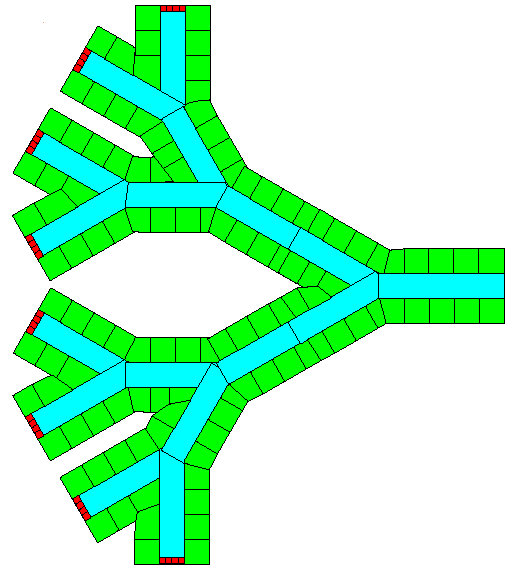
- Save the image in a bit mapped format that the PIL-Image library supports; jpg, png or bmp.
- If you have a different image format you will need to convert it to one of the formats listed above.
- Finally, you need the CC3D code to read the image and convert it into a set of cells in CC3D.
Download and unzip this zip file
- It is best if you know how big the image is and setup CC3D so that the simulation window is at least that big. Many image viewing programs will tell you the size of the image in pixels. Or, if you setup the CC3D code outlined below it will tell you what the image size is.
- The image you want to use can be anywhere on your computer but it is convenient to place it in the "Simulation" folder.
- Edit the file in the project called "CC3D_import_image_Complex_map_cells_Parameters.py" which defines the input file and color mapping you want.
- define the path and filename to your image:
inPath="C:/Users/Username/Desktop/CC3D_importing_images/Simulation/"
inImage="8_4_2_1_part_tiny.bmp"
- note that in windows you should use either a double backslash in the path or convert window's backslash to slashes.
- Define the size of the CC3D layout (which normally matches the dimensions of your image)
xDim = 149  # image x width
yDim = 103  # image y width
- Define the color ranges that map to each cell type
# The color and cell type number map, as a list of dictionaries.
# Note that the cell type names used in the pif file are derived from the CC3D id's below and the cell names
# in the main CC3D python script.
# for each cell type, represented by a particular color, create a line in the table below. Specify the minimum and maximum
# values (e.g., rMin and rMax for the red color channel) for each cell type. The min and max values can be the same.
# Recommend to use the first line as black for cell borders and the second for white for Medium (cell type 0).
cmap=[]
cmap.append({'rMin':  0, 'rMax':  5,   'gMin':  0, 'gMax':  5,   'bMin':  0, 'bMax':  5, 'CC3Did':5})  # black, cell border
cmap.append({'rMin':250, 'rMax':255,   'gMin':250, 'gMax':255,   'bMin':250, 'bMax':255, 'CC3Did':1})  # white, medium=0 (cell wall=1 in the demo)
cmap.append({'rMin':250, 'rMax':255,   'gMin':  0, 'gMax':  5,   'bMin':  0, 'bMax':  5, 'CC3Did':3})  # red, source
cmap.append({'rMin':  0, 'rMax':  5,   'gMin':250, 'gMax':255,   'bMin':  0, 'bMax':  5, 'CC3Did':2})  # green, hep
cmap.append({'rMin':  0, 'rMax':  5,   'gMin':250, 'gMax':255,   'bMin':250, 'bMax':255, 'CC3Did':4})  # cyan, blood
Update the list of cell types and names in the "CellType" plugin block in the main python script "CC3D_import_image_Complex_map_cells.py". You can replace the lines that are already there using them as a template. It is important the "Medium" is defined as type ID 0 (zero) and that all of the cell types are "Freeze". Just add the cell names you want and use the "TypeId":"1" syntax to link a cell type name to the number used in the parameters layout described above.
PluginElmnt=CompuCell3DElmnt.ElementCC3D("Plugin",{"Name":"CellType"})
# Listing all cell types in the simulation
PluginElmnt.ElementCC3D("CellType",{"TypeId":"0","TypeName":"Medium"})
PluginElmnt.ElementCC3D("CellType",{"TypeId":"1","TypeName":"wall","Freeze":"1"})
PluginElmnt.ElementCC3D("CellType",{"TypeId":"2","TypeName":"hep","Freeze":"1"})
PluginElmnt.ElementCC3D("CellType",{"TypeId":"3","TypeName":"source","Freeze":"1"})
PluginElmnt.ElementCC3D("CellType",{"TypeId":"4","TypeName":"blood","Freeze":"1"})
PluginElmnt.ElementCC3D("CellType",{"TypeId":"5","TypeName":"cellborder","Freeze":"1"})- Run the CC3D project, which:
- Reads the image file
- Creates a cell field based on the image and the color mapping
- Outputs a .piff file based on your image.
- The piff file is written in the same directory that had the original image in it.
- If your input image was "my_image.bmp", the output file will be "my_image.bmp.piff"
 (click for a larger version)
- Note that Player has its own color mapping scheme. If you want "red" cells in your input image to show as red cells in Player you will need to go to Player's "Tools" menu, "Configuration ...", "Cells/Colors" tab and change the colorings.
By default, the CC3D projects is setup to convert the file named "8_4_2_1_verysmall.bmp", which is in the zip folder.